EPIC-WSC-DS · Edition 3
Water Supply Controls Drawing Set
The wiring and panel drawings that accompany the Water Supply Controls booklet.
On request15 pages


Components & Specification · Technical booklet
How an EPIC system is filled, held and stopped. Four control architectures, the electrical work behind each of them, and the settings that make them work in sand.
Water Supply Controls is a working guide to the valves, timers, transformers, relays, floats and wiring that decide when water enters the EPIC chambers, how slowly, and when it stops. It is written for the electrical contractor wiring the panel, the irrigation contractor commissioning the field, and the engineer of record.
Every scheme performs the same four duties: admit, meter, hold and stop. The booklet compares four control architectures side by side: pump-less on mains pressure, pumped recirculation, a creek feature with sump return, and off-grid solar. Each has its own section built around a schematic, the comparison table says when to use each scheme and what to watch for, and two governing rules apply to all of them.
The electrical sections cover the pre-assembled control unit, power and earthing, the extra-low-voltage side and conductor sizing, wiring the zones and pumps with one timer or two, and the relay and float interlocks for pump and level control. The booklet closes with the published rates and shared settings, the charging programme for a new bed, and commissioning and fault-finding checks.
It is read with EPIC Water Delivery and Drainage for the governing hydraulic figures, the Installation Sequence and Volume 2, Construction Specification. The thirteen reference drawings are issued separately as the EPIC Water Supply Controls Drawing Set, which the back page lists among the documents issued with the booklet.
The wiring and panel drawings that accompany the Water Supply Controls booklet.
On request15 pages
The governing hydraulics: flow rates, profile storage and charging behaviour.
On request26 pages
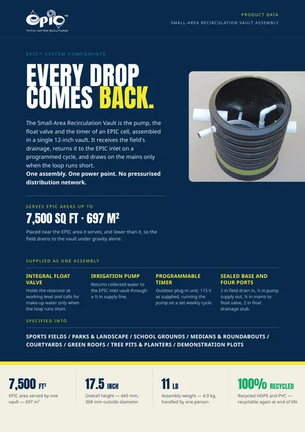
The small-area vault for cells that recirculate water rather than discharge it.
Registered3 pages
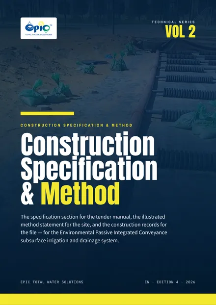
The CSI three-part specification section, the illustrated method statement and the construction record forms.
Registered84 pages
Working on a project? Send us the drawings, the bill of quantities or the question.
Talk to usPublished by EPIC Total Water Solutions LLC, Reno, Nevada. Issued in the Middle East and North Africa by Xpitrade General Trading LLC.