EPIC-WSC-01 · Edition 3
Water Supply Controls
How a system is filled, held and stopped: four control architectures, the electrical work behind each, and the settings that suit sand.
Registered15 pages


Components & Specification · Drawing set
Thirteen reference plates at full sheet size, issued with the Water Supply Controls booklet. Each carries a strip saying what it shows, the figures that govern it, and the booklet section it belongs to.
The drawing set is the illustrated companion to the EPIC Water Supply Controls booklet. Its thirteen plates show the control schemes, process diagrams and wiring arrangements the booklet describes, each at full sheet size with a strip beneath it keyed to the relevant booklet section.
The plates follow the booklet's four control architectures. The pump-less mains-pressure scheme is shown as a system schematic, a three-dimensional view and a section through the EPIC module. Pumped recirculation has a three-dimensional view and a process schematic with programmable control. The creek and sump return scheme has a three-dimensional view and an instrumented P&ID, and the off-grid solar scheme a three-dimensional view and a full DC schematic.
The last four plates cover wiring where two areas are controlled: simultaneous power from one timer, drawn as an isometric view, a ladder diagram and a variant of it for checking the common routing, and independent timers, each with its own transformer, for two areas on separate programmes.
The index states that the sheets are drawing-office records, not contract documents, and that where a plate and the booklet differ, the booklet governs. On site, the plate for the architecture being built is printed, marked with the flow-control settings at commissioning, and filed with the commissioning record.
How a system is filled, held and stopped: four control architectures, the electrical work behind each, and the settings that suit sand.
Registered15 pages
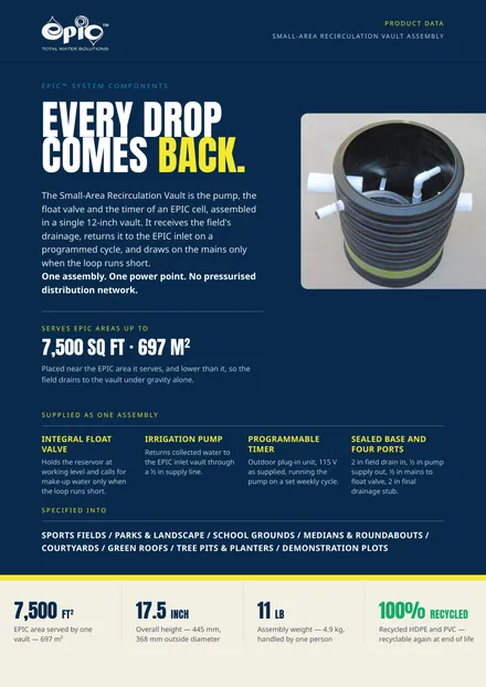
The small-area vault for cells that recirculate water rather than discharge it.
Registered3 pages
The outlet control vault at the discharge end of the manifold.
Registered1 page
The governing hydraulics: flow rates, profile storage and charging behaviour.
On request26 pages
Working on a project? Send us the drawings, the bill of quantities or the question.
Talk to usPublished by EPIC Total Water Solutions LLC, Reno, Nevada. Issued in the Middle East and North Africa by Xpitrade General Trading LLC.